logo
Home
Products
About Us
Factory Tour
Quality Control
Contact Us
Request A Quote
Blog
Company News
Home ProductsFemale Header Connector

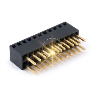
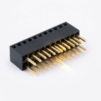
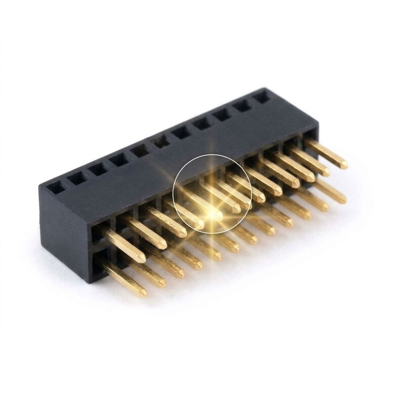
2.54mm Pitch Bottom Entry Female Header Connector Pass Through Socket Dual Row PCB Mount

2.54mm Pitch Bottom Entry Female Header Connector Pass Through Socket Dual Row PCB Mount

  • 2.54mm Pitch Bottom Entry Female Header Connector Pass Through Socket Dual Row PCB Mount
  • 2.54mm Pitch Bottom Entry Female Header Connector Pass Through Socket Dual Row PCB Mount
2.54mm Pitch Bottom Entry Female Header Connector Pass Through Socket Dual Row PCB Mount
Product Details:
Place of Origin: Guangdong, China
Brand Name: CNJWY
Certification: ISO 9001:2015, RoHS, UL
Model Number: CNJWY-FH254-BE
Payment & Shipping Terms:
Minimum Order Quantity: 1000 Pieces
Price: USD 0.18-0.65 / Piece
Packaging Details: 1000 pcs per anti-static bag, 10 bags per export carton
Delivery Time: 7-15 working days for production, 3 days for stock items
Payment Terms: T/T, L/C at sight, Western Union, PayPal
Supply Ability: 5000000 Pieces per Month
Contact Now
Detailed Product Description
Pitch: 2.54mm Rows: Dual Row
Positions: 2 X 2 To 2 X 40 Entry Style: Bottom Entry, Pass Through
Mating Direction: From Below The PCB Contact Material: Phosphor Bronze
Contact Plating: Gold Flash Over Nickel Insulator Material: PA6T, UL 94V-0
Current Rating: 3A Per Contact Voltage Rating: 250V AC
Operating Temperature: -40 C To +105 C
Highlight:

Bottom Entry Female Header

,

Pass Through PCB Socket

,

2.54mm Dual Row Header

A conventional female header mates from above, which forces the mating board to sit on top of the host PCB. This bottom entry version reverses the geometry: the contact cage opens downward through a window in the insulator, so a male header can enter from underneath the board. That single change lets a daughter card sit flush against the back of the main board, reducing total assembly thickness by the full body height of the connector.

The pass through design also simplifies rework. Because the pin field is accessible from below, an operator can probe or desolder the joint without lifting the upper board, and the mating header can be a simple turned or stamped male strip with no shroud. The insulator keeps standard 2.54mm spacing and dual row geometry, so the part drops into footprints that were originally laid out for an ordinary top entry socket.

Key Features
  • Bottom entry geometry: The mating post enters from below the PCB, letting the daughter card sit flush against the main board.
  • Flush stacking: Removes the body height from the total assembly thickness, which matters in slim enclosures.
  • Probe accessible joints: The pin field can be reached from underneath, so rework and inspection do not require lifting the upper board.
  • Standard 2.54mm footprint: Drops into land patterns already laid out for a top entry dual row socket.
  • Gold flash over nickel: Stable contact resistance with a barrier layer against humidity and industrial sulphur.
  • Simple male mating: Accepts plain stamped or turned male strips, so the mating side needs no shroud or keying hardware.
Technical Specifications
ParameterSpecification
Pitch2.54mm
Rows2 rows
Positions2 x 2 to 2 x 40
Entry StyleBottom entry, pass through
MountingThrough hole, vertical
Contact MaterialPhosphor bronze
Contact PlatingGold flash over nickel
InsulatorPA6T, UL 94V-0
Current Rating3A per contact
Voltage Rating250V AC
Contact Resistance20 milliohms maximum
Insulation Resistance1000 megohms minimum
Dielectric Withstanding500V AC for one minute
Operating Temperature-40 C to +105 C
Durability300 mating cycles
Applications

Bottom entry sockets are used wherever the stacking order is fixed by mechanics. Portable instrument enclosures often mount the display board behind the main board, so the electrical connection has to come from behind. Automotive control modules use them to attach a daughter card on the underside of a main PCB inside a shallow housing. They also appear in card readers and access control units where the reader board sits under the controller board, and in test adapters where an operator needs to probe the joint side while the connector is mated.

Customization and Engineering Support

We can mould the bottom window to accept either 0.64mm square posts or 0.5mm round pins, and can add a locating peg or a mounting flange for panel alignment. Positions from 2 x 2 to 2 x 40 are cut from strip without tooling charges. Optional variants include selective gold at 0.76 micron, a closed top face so flux cannot enter from above, and a matched male header supplied as a pair from the same drawing. Engineering can also advise on solder paste volume for the bottom entry window, which is the most common source of defects in this configuration.

Packaging & Quality Assurance

Each connector is packed 1000 pieces per anti-static bag with a desiccant sachet, ten bags per export carton. The bags are cushioned with foam so the contact cage cannot be deformed through the bottom window, which is the most delicate feature of this part. Cartons carry the CNJWY neutral label, stay below 15 kg gross and are sealed with tamper evident tape. Sea freight is palletised and stretch wrapped against container humidity, and air shipments are foam lined. Own-brand cartons, barcode labels and drop tested inner packaging are offered, and each lot ships with a dimensional report, a plating thickness certificate and a RoHS declaration.

Contact Details
ShenZhen JWY Electronic Co.,Ltd

Contact Person: Mr. Steven Luo

Tel: 8615013506937

Fax: 86-755-29161263

Send your inquiry directly to us (0 / 3000)

Other Products
15013506937