logo
Home
Products
About Us
Factory Tour
Quality Control
Contact Us
Request A Quote
Blog
Company News
Home ProductsFemale Header Connector

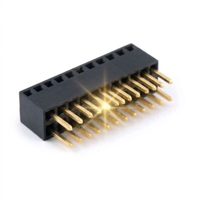
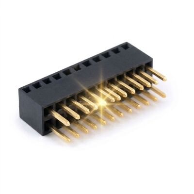
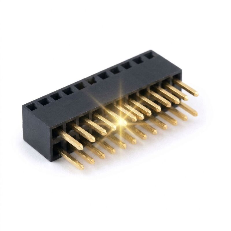
2.54mm Pitch Long Solder Tail Female Header Connector Dual Row 2x20 Extended Pin PCB Socket

2.54mm Pitch Long Solder Tail Female Header Connector Dual Row 2x20 Extended Pin PCB Socket

  • 2.54mm Pitch Long Solder Tail Female Header Connector Dual Row 2x20 Extended Pin PCB Socket
  • 2.54mm Pitch Long Solder Tail Female Header Connector Dual Row 2x20 Extended Pin PCB Socket
2.54mm Pitch Long Solder Tail Female Header Connector Dual Row 2x20 Extended Pin PCB Socket
Product Details:
Place of Origin: Guangdong, China
Brand Name: CNJWY
Certification: ISO 9001:2015, RoHS, UL
Model Number: CNJWY-FH254-LT2R20
Payment & Shipping Terms:
Minimum Order Quantity: 1000 Pieces
Price: USD 0.22-0.80 / Piece
Packaging Details: 1000 pcs per anti-static bag, 10 bags per export carton
Delivery Time: 7-15 working days for production, 3 days for stock items
Payment Terms: T/T, L/C at sight, Western Union, PayPal
Supply Ability: 5000000 Pieces per Month
Contact Now
Detailed Product Description
Pitch: 2.54mm Rows: Dual Row
Positions: 2 X 2 To 2 X 20 Solder Tail Length: 15.0mm Extended Tail
Mounting Type: Through Hole, Vertical Contact Material: Phosphor Bronze
Contact Plating: Gold Flash Over Nickel Insulator Material: PA6T, UL 94V-0
Current Rating: 3A Per Contact Voltage Rating: 250V AC
Operating Temperature: -40 C To +105 C
Highlight:

Long Solder Tail Header

,

Extended Pin Female Socket

,

2x20 Thick Board Header

Standard header tails assume a 1.6mm board. Put the same part into a 3mm backplane, a press fit assembly or a board that is soldered from the underside, and the tail either fails to protrude or fails to form a fillet. This 2.54mm dual row female header carries 15mm extended tails so the contact reaches through thick laminate, leaving enough length on the far side for a proper wave or selective solder joint regardless of board thickness.

Long tails are only useful if they stay straight. Each tail is guided through a moulded channel in the insulator so that it enters the plated hole perpendicular, and the extension is formed from the same phosphor bronze strip as the contact spring rather than being a separately staked pin. That keeps the electrical path continuous and avoids the resistance step that staked tails introduce. The insulator is PA6T, and gold flash over nickel protects the contact interface.

Key Features
  • 15mm extended tails: Reaches through thick laminate and backplanes while leaving a full solder fillet on the far side.
  • Moulded tail channels: Each tail is guided perpendicular to the board, preventing the angled insertion that cracks thick board joints.
  • One piece contact: Tails are formed from the same strip as the spring, so there is no staked joint or resistance step.
  • Bottom side solderable: Extra tail length allows selective soldering from the underside where topside access is blocked.
  • Standard 2.54mm grid: Mates with ordinary dual row male headers and retains the familiar PCB footprint.
  • Gold flash over nickel: Stable contact resistance through the thermal cycles of heavy board soldering.
Technical Specifications
ParameterSpecification
Pitch2.54mm
Rows2 rows
Positions2 x 2 to 2 x 20
Solder Tail Length15.0mm
MountingThrough hole, vertical
Contact MaterialPhosphor bronze
Contact PlatingGold flash over nickel
InsulatorPA6T, UL 94V-0
Current Rating3A per contact
Voltage Rating250V AC
Contact Resistance20 milliohms maximum
Insulation Resistance1000 megohms minimum
Dielectric Withstanding500V AC for one minute
Operating Temperature-40 C to +105 C
Tail Straightness0.20mm maximum deviation
Durability500 mating cycles
Applications

Extended tail headers are used where the board is thicker than the connector was designed for. Backplanes in industrial racks, power distribution boards with heavy copper, and chassis that stack two boards on a shared pin field all need tails that reach. They also suit assemblies that are soldered from below, where the operator needs visible tail protrusion to confirm a joint, and press fit adapters that use a long tail as a compliant lead into a socket on the far side of the laminate.

Customization and Engineering Support

Tail lengths of 5.0, 8.0, 11.0, 15.0 and 20.0mm are available from the same contact system, and positions from 2 x 2 to 2 x 20 carry no tooling charge. We can add a moulded standoff collar that holds the body clear of the solder mask, mould locating pegs, and supply selective gold at 0.76 micron for high reliability programmes. Where boards exceed 4mm, our engineers will review the hole diameter and recommended wave solder parameters so that the tail length is matched to the actual laminate thickness.

Packaging & Quality Assurance

Each connector is counted into anti-static shielding bags with a desiccant sachet and a humidity indicator card, then packed into export-grade corrugated cartons carrying the CNJWY neutral label. Inner foam inserts keep the contact field clear of the carton wall, and carton gross weight is held under 15 kg so that air freight handling limits are respected. Sea freight shipments are palletised, stretch wrapped and strapped against container humidity. Own-brand labels, barcoded cartons and drop tested inner boxes can be supplied for distributors, and every lot ships with a dimensional report, a plating thickness certificate and a RoHS declaration taken from the same production batch.

Contact Details
ShenZhen JWY Electronic Co.,Ltd

Contact Person: Mr. Steven Luo

Tel: 8615013506937

Fax: 86-755-29161263

Send your inquiry directly to us (0 / 3000)

Other Products
15013506937